
Sunday, May 31, 2026
Home Blog Page 86

Accurate 3D measurement of magnetic fields for automotive gear selector

0

Conventional linear Hall sensors, Hall switches and angle sensors are only able to recognize magnetic field components that are perpendicular to the surface of the chip; Giant Magneto-Resistive (GMR) angle sensors measure only the planar-oriented field components. However, the TLE493D-W1B6 sensor is capable of simultaneously determining the x, y, and z coordinates of the magnetic field.

Recognition of the magnetic field components of all three axes provides a holistic, three dimensional image of the magnetic field in which the sensor lies. Any movement of the magnet leads to a change in at least one of the magnetic field components, which is recognized by the 3D sensor.

The three dimensional sensor system is made possible by the integration of both vertical and horizontal Hall plates into a single sensor chip. The vertical Hall plates detect the planar-oriented x and y field components, while the horizontal Hall plate detects the vertically oriented field component (z direction).

Several innovative, patented concepts were applied in the development of the sensor. Users can define a magnetic field corridor for each magnetic field direction such that if the measured magnetic field lies outside of the corridor, the sensor sends an alert signal to the connected microcontroller. A further development goal was the reduction of power consumption. Thanks to innovative design technologies, such as the energy-saving oscillator, the sensor’s power consumption was reduced to only a few nanoamperes – 7 nA when in “power down” mode, for instance. The result is a silicon component that fits into a small package despite its large functional scope. The TSOP-6 case with six pins is only 2.9 x 1.6 mm in size – making it smaller than any other 3D magnetic sensor on the market.

Because of its low power consumption and its integrated magnetic field alert, the TLE493D-W1B6 is suitable for use in applications that must detect regular changes in position while using very little power. In addition, it allows the realization of precise, energy-saving system concepts that can be activated by a sensor alert. The sensor’s magnetic field alert, for example, can be used to wake up the microcontroller from its power-saving “sleep” mode. This alert is triggered whenever a change of the magnet’s position alters the magnetic field.

The sensor is equipped with a digital output that uses a two-wire I²C standard interface. This allows high communication speed and bus mode.

Qualified in accordance with the AEC-Q100 automotive standard, the device allows customer systems to comply with the highest quality standards and various environmental regulations. In addition, all relevant ISO 26262 documents are provided in order to fulfill functional safety system requirements.

Architecture and Primary Features

The sensor architecture consists of three primary function units (Figure 2) – power mode control unit, sensor unit and communication unit.

The power mode control unit serves to distribute energy in the integrated circuit (IC) as well as controlling sensor activation.

The sensor unit, which contains the vertical and horizontal Hall plates and a temperature sensor, measures the magnetic field in the x, y, and z directions. Use of vertical Hall plates for both planar magnetic field components (x and y direction) allows the sensor to achieve outstanding magnetic reconciliation accuracy (±1 %), enabling precise angle measurements. Each x, y, and z Hall plate is connected in series to a multiplexer which is connected to an analog-to-digital converter (ADC). The temperature sensor is also connected to the multiplexer and can be activated if desired.

The microcontroller always has access to the communication unit through an I 2C interface and to the register data in order to read out the register values. Values for the three axes and the temperature are stored in separate registers. While the interface fulfills the I 2C fast-mode specification (400 kBit/s), an optimized electrical circuit allows data rates above 1 MBit/s to be supported. The sensor can also be used in an I 2C bus scheme with other devices in accordance with the I 2C protocol guidelines.

During 3D magnetic field detection, the TLE493D-W1B6 offers 12-bit data resolution for every measurement direction. This enables high data resolution of 0.098 mT/bit (least significant bit, LSB), which allows even the smallest movement of the magnet to be measured. Linear measurements of the magnetic field (B) in relation to each of its axes (Bx, By, and Bz) are also possible for the large linear field range (±150 mT). This means an even longer linear magnetic movement (up to 4 cm) can be measured. The large measurement range also enables a simple, robust, flexible magnetic circuit layout.

Flexible Power Modes for Lowest Power Consumption

After each measurement cycle, the sensor transmits a strong interrupt signal to the connected microcontroller, which can then read out the magnetic and temperature values from the registers. The sensor’s interrupt signal can be used to wake up the microcontroller system from its sleep mode. If the entire system is in sleep mode and only activated in the read-out phase, the total power consumption of the system as a whole is reduced dramatically.

The TLE493D-W1B6 can operate in different modes. Individual operating modes vary by their numbers of measurement cycles per second and the sensor can be set to the desired mode flexibly during operation.

In power down mode, all functional blocks are shut down. In this mode, no magnetic measurements are performed and power consumption drops to 7nA.

In “fast” mode, the readout speed is optimized. While the measurement result is read out, the next magnetic field measurement can be performed. This mode is particularly suited to applications for which very fast magnetic movements must be detected. The sensor’s power consumption is, at most, 3.7 mA at a sampling rate of about 8 kHz, corresponding to 8,000 measurement cycles/second.

A total of eight different “low power” modes have been implemented in the TLE493D-W1B6. In all of these modes, the sensor regularly and autonomously wakes up out of power down mode in order to perform magnetic measurements. The power consumption depends on the number of measurement cycles/second (see Figure 3).

In “master-controlled” mode, the sensor can be flexibly read out according to the requirements of the application. After each measurement, the sensor waits until the microcontroller (master) has read out the register. Depending on the application conditions, the read-out process can be performed immediately or with a slight delay. As soon as the microcontroller has detected the magnetic values, a new sensor measurement cycle is triggered. This mode is particularly useful when several TLE493D-W1B6 sensors are connected through an I²C bus for the detection of large linear movements. The microcontroller decides which sensor’s data is most relevant and triggers the corresponding sensor.

Application: Gear Selector in a Mid-Range Car

A magnetic 3D sensor is very useful in detecting the position of the gear selector in an automobile as the existing ‘state-of-the-art’ solution, which uses at least six Hall switches, can be replaced by a single 3D sensor. Because the TLE493D-W1B6 has the same case dimensions as modern Hall switches, a great deal of space, as well as money, can be saved.

Using a gear selector for a current mid-range car as an example, here we will evaluate how the 3D sensor provides an alternative to the current solution.

Figure 4 (left) shows six gear selector positions on a circular arc at intervals of about 6 °. The original gear selector is detected by means of a Hall switch in each of the six selector positions. These six Hall switches can be replaced by a single TLE493D-W1B6 3D sensor.

For a robust magnetic design, the following parameters should be used:

  • Magnet shape: Cuboid shaped (7 x 5 x 3 mm)
  • Magnet material: NdFeB
  • Remanence: 1 T
  • Sensor: TLE493D-W1B6
  • Air gap between sensor and magnet: 4 mm
  • Magnetization: Axial
  • Lever arm: 1.3 cm
  • Swept angle: 0 … 30 °
  • Six positions result in a resolution of 6 ° per position

The parameters above allow linear behavior between the mechanically deflected angle and the calculated spherical angle Theta (Ɵ). The spherical angle is calculated from the sensor’s x, y, and z components.

Functional Safety

The TLE493D-W1B6 is also equipped with test functions that make possible malfunction detection during operation, allowing the complete sensor signal chain to be assessed at any time. The test delivers a defined value that the microcontroller can compare with the expected value. If the expected value is obtained, the master does not need to initiate further measures. Test times are significantly lower than 1 ms.

Alert Function

A further intelligent feature of the TLE493D-W1B6 is the magnetic field alert. For all three magnetic field directions, a corridor can be determined in milliTeslas for magnetic field strength. The magnetic field is cyclically measured in the set mode and compared with this corridor. If the measured magnetic field value remains within the corridor in all three directions, the sensor suppresses the interrupt signal. If the measured magnetic field value exceeds the upper corridor value or falls below the lower one, the sensor initiates an interrupt and wakes up the microcontroller (Figure 6). When the master (microcontroller) becomes active, it reads out the magnetic field values from the registers. The corridor can be set for all three axes at any time and independently of each other. This allows the thresholds to be adjusted in reaction to changes in mechanical positions.

Using the magnetic field alert means that the entire microcontroller system can be set to sleep mode, with the sensor only waking the microcontroller and the connected systems when the magnetic position indication changes. This enables the development of systems that save a great deal of energy, but are nevertheless capable of reacting quickly to a change in position.

Summary

The TLE493D-W1B6 sensor provides precise and energy-efficient 3D magnetic field detection for various applications. Flexible operating modes offer dedicated and scalable system designs with a wide measurement range for precise position determination and very low power consumption. The integrated magnetic field alert can wake up the microcontroller systems in order to inform them of a change in position.
Smart fuse reduces cost, weight of automotive wiring harness

0

From a system point of view, however, the implementation of a more intelligent, electronic fuse offers the potential to cut total cost, as well as to reduce the weight of the vehicle substantially. Now ams has introduced a reference design board which shows the industry a design concept for an accurate yet simple intelligent fuse, and which gives OEMs the opportunity to evaluate the concept, understand its advantages and cost, and simulate its operation in complex power systems.

The traditional fuse: slow, inconvenient, cumbersome

Thermal fuses are slow and inconvenient. The typical fuse in a car is blown after around 20-50ms when subject to 10x its nominal current. And because a fuse cuts out when triggered, it has to be replaced after every over-current event. This is why cars include a special housing at a central point, to provide the easiest possible access when a fuse needs to be replaced.

In fact, when today’s cars have so much modern technology inside them, such as touchscreens, voice recognition and sophisticated driver-assistance systems, the antiquated tool and obscure process for replacing a traditional fuse seem out of place.

A modern electronic fuse does away with this ancient technology. Instead, the dashboard can display diagnostic information on the potential location of the fault that caused the fuse to be triggered, and guidance on the way to repair it.

In addition, an electronic fuse is as much as four orders of magnitude faster, dramatically shortening the exposure of the circuit it protects to damaging current surges. It can also provide a much more precise maximum-current trigger point. This gives the potential to reduce cable diameter when compared to thermal fuse protection, which requires the designer to allow for a broadly defined maximum current range, rather than a specific – and lower current value.

Another great advantage of the electronic fuse is apparent in the configuration of the power network. Electronic fuses can be placed virtually anywhere in the car; unlike thermal fuses, they do not need to be gathered in one fuse box. One benefit of this is shorter cable runs, and a consequent reduction in cost and weight.

It also enables the power system designer to implement for the first time tree topologies, which are easy to manage, and even ring topologies for advanced safety features. Tree topologies support the use of very much thinner cables, because they allow the power controller to switch off certain portions of a circuit for a certain period to keep the load on the entire circuit below a pre-determined maximum value.

Quantifying the potential for weight reduction

It is clear, then, that replacing thermal fuses with electronic fuses offers the potential to reduce the size and weight of the cable harness. But by how much?

A couple of decades ago, cables in cars mainly carried loads rather than signals. In the case of an indicator, for instance, the stalk at the steering wheel closed a contact which directly connected the indicator’s relays to the battery.

In the 1990s, car manufacturers began to introduce power networks. The goal was to keep load-carrying cables as short as possible, and to use thinner signal cables whenever possible. So today’s indicator stalk does not close a load contact: instead, a sensor detects that the indicator has been switched on, triggering a pair of electronic control units (ECUs) to send this information to the main front and rear body units. It is these body units which switch power on and off to the indicator lights.

Had no other developments occurred in the car, this would have reduced the total weight of the cable harness. In practice, however, cars today include so many more electrical and electronic functions than cars did in the 1990s that the weight saving has been more than eaten up by the requirement for additional network connections. In fact, a modern mid-range car carries more than 1.5km of cable weighing more than 40kg.

And of course, these cables require protection. This often leads the system designer to struggle with the best way to trade off improvements in safety, comfort and functionality against the desire to reduce weight and cost.

Take the example of an electric sun-roof. The design specification requires that the roof will open even when its seal is frozen. Breaking the grip of ice calls for a high current through the sun-roof’s electric motor, as much as 30A.

But the specification for the circuit’s thermal fuse cannot be for 30A, since ageing reduces the fuse’s current rating*: a margin of 20% has to be added. But 36A is not a standard rating for off-the-shelf fuses, so the sun-roof designer is forced to specify a 40A fuse.

This in turn affects the cable specification. For the motor’s 30A maximum current, a 2.5mm² cable would be sufficient. The power network design must also be specified to withstand a maximum 70°C operating temperature. Assuming it takes 50ms to melt the fuse at 400A – ten times the nominal 40A rating – the temperature of the cable might rise far above the maximum temperature rating of 105°C for a standard cable in a car in the event of a current surge.

As a result, the sun-roof designer is forced to specify the next thicker grade of cable: in this case, 4mm², which is 40% heavier, and 40% more expensive.

By contrast, an intelligent, application-oriented electronic fuse, which does not age, could be designed to be triggered at an exact current value of 30A (or higher), enabling the use of 2.5mm2 cable.

The authors’ estimate is that some 5-8kg of copper can be removed from the car by replacing thermal fuses with electronic fuses. At the time of writing, the cost of copper was around €6.50/kg, providing an estimated cost saving in copper alone of up to €52. In addition, the weight saving improves the vehicle’s fuel efficiency, helping the car manufacturer to avoid the proposed €95/g of CO2 levy to be imposed by the European Union when fleet-wide fuel consumption rises above a certain threshold.

Besides of being a very cheap component, there are numerous and serious drawbacks in using simple fuses. But there are alternatives

But an intelligent fuse can provide even more benefits:

  • it can measure the temperature locally
  • it can enable intelligent power switching

This latter feature lets the system designer reduce even further the weight of copper in multi-function supply cables. Take the example of a front door. This has multiple electrical functions, including:

  • mirror positioning
  • mirror opening and closing
  • mirror heating
  • indicator lighting
  • electric window motor

All of these functions could operate simultaneously; in this case, the door’s power circuit would need to support a high peak load current, and this would call for a cable with a large diameter. The alternative is – at the cost of slightly compromising the user’s convenience – to disable certain functions by default. For example, the mirror heater may be disabled while the window motor is in operation. It might in fact only be necessary to stop the current to the heater for a few milliseconds, when the motor current spikes as it starts up. So the blocking of certain functions might either be minimal or, if prolonged, the user may be informed in the dashboard display.

In either case, precise and continuous current measurement, which is performed by default by an intelligent fuse, ensures that the current flowing through every single electrical sub-system is known, and so the power consumption and peak current requirement may both be managed in an intelligent and granular way. This will, of course, require the development of new and complex software.

Intelligent automotive fuses: a demonstration circuit

Now ams has developed a demonstration board which contains all the functional blocks required to realise an intelligent fuse (see Figure 1). In evaluating the circuit, automotive manufacturers are expected to assess:

  • whether the accuracy and precision of the current and temperature measurements are at the right level
  • whether the circuit offers the right number of channels

The feedback from manufacturers will influence the final specification of a chip-scale version of this demonstration circuit, now in development at ams. The new fuse consists of a switching element and a current measurement element.

In the IC version of the circuit, the switch will be realised as an internal gate driver and an external MOSFET. The drivers have to operate at high speed, because they need to frequently switch heavy loads, and, in order to avoid excessive switching losses, the MOSFET should spend as little time as possible in the linear region.

Like a conventional thermal fuse, the switch must be on the high side. This means that the driver needs an additional charge pump in order to raise the voltage far enough above the battery voltage to drive the MOSFET.

Accurate current measurement on the high side

A difficult part of the circuit to realise – and the reason why no semiconductor manufacturer before now has implemented this simple but high-performance design – is the high-side current measurement.

Despite being on the high side, this current measurement circuit must offer high accuracy if the circuit is to provide the benefits – such as weight reduction and intelligent power management – described above. Fortunately, ams has developed a technology which can achieve accurate high-side current measurement. What is more, it measures current directly on the board’s copper traces, avoiding the need for an expensive alloy precision shunt resistor.

On the demonstration board, the current measurement components are placed directly on top of the copper traces so that they can measure their temperature as well as the current flow. This eliminates the need for external sensors, while allowing for compensation for the temperature coefficient of the copper. (The dimensions of the copper trace must be specified with reasonable accuracy.)

With this technique for direct measurement on a trace, currents up to around 50A may be measured, using two layers of a four-layer board. Since the circuit is making high-side measurements, there is also a need for level shifters to provide a voltage that the ADC can handle. In the demonstration board, the circuit achieves current-measurement accuracy of ±2% over the operating temperature range. This can be improved if necessary.

The circuit also provides for direct cut-off, bypassing the digital functional block. This ensures that the fuse can switch within a maximum of 20µs when subject to a large current surge. Implementing the comparator and level shifter for this function is another demanding circuit-design challenge.

In terms of board layout, several current paths are routed together, and covered on the backside with an additional thermal mass (made of copper). This ensures that they are thermally coupled, and so a single temperature measurement may be applied to the entire circuit, with compensation for thermal resistance implemented in the microcontroller

The ADC itself has a chopper architecture which produces a zero offset: this enables the circuit to measure current accurately even at low currents. Level shifters drop the analogue voltage over the shunts to the ADC’s voltage domain. Dechopping is implemented in the digital filter of the Sigma-Delta ADC.

A common objection to chopper architectures is that they generate noise. But in this ams design, chopping with ringing cancellation is performed in the analogue domain, and dechopping in the digital (see Figure 3). As a result, noise is negligible, while the offset in the signal path of the current channel is entirely eliminated.

Temperature measurement

In the ams circuit, measurement of the MOSFET’s temperature is performed by external temperature sensors, since most MOSFETs’ internal temperature measurement is not accurate enough. With an additional comparator, this allows for direct over-temperature shut-down, bypassing the digital circuit in the same way as for the over-current shut-down function.

Digital functional block

Figure 1 shows a microcontroller which performs a number of digital functions:

  • Digital de-chopper (demodulator) for current measurement
  • Resistor temperature compensation for the copper shunts
  • DAC shut-down signal for over-current and over-temperature
  • End-of-line storage of calibration values for current paths
  • Software to calculate exact current values for transfer to an ECU
  • Communication interface
  • Management of safety features
  • Programming of over-temperature and over-current trigger characteristics for up to four channels

When implemented as an IC, it is intended that, wherever possible, digital functions should be implemented as state machines; the device will not include a microcontroller. This approach is simpler and cheaper, it consumes less power, and it better supports the requirement for functional safety.

It should be said that the analysis of the functional safety of this circuit is today in its early stages. The plan for implementing the IC product provides for an ASIL A rating, with provision for a higher safety rating if required by the industry. Since the use of intelligent fuses calls for some external software if the full benefits are to be enjoyed, a full functional safety analysis can only be made in the context of the final application.

One fact, however, should not be forgotten: a melted fuse has no ASIL level at all. In terms of functional safety, then, as well as system cost, fuel efficiency, performance and functionality, the intelligent fuse demonstrated by ams is far superior to the traditional thermal fuse.

Summary

The steady growth in the number of electronic, electrical and electro-mechanical functions in cars has given rise to many innovations in the design and operation of automotive power systems. In one domain, however, the car remains stuck in a technological Stone Age: the device of choice for circuit protection is still the fusible cut-out (fuse).

Its use continues in spite of its numerous and serious drawbacks. This is because the traditional fuse has one, very powerful attribute in its favour: its unit cost is verylow.

Looked at from a system point of view, however, the implementation of a more intelligent, electronic fuse offers the potential to cut total cost, as well as to reduce the weight of the vehicle substantially. Now ams has introduced a reference design board which shows the industry a design concept for an accurate yet simple intelligent fuse. It gives OEMs the opportunity to evaluate the concept, understand its advantages and cost, and simulate its operation in complex power systems.

This article details the drawbacks of the traditional thermal fuse. It then describes the operation of the new demonstration circuit. It shows how innovative high-side current measurement directly on the board’s copper traces, together with fast analogue over-temperature and over-current shut-down circuits, provide a simple, low-power, low-cost and high-performance alternative to the thermal fuse.


How your car can check your daily health

0

Health freaks may wear a fitness tracker on their wrist, but there’s also something just as valuable coming soon for the non-freaks among us. By incorporating sensor and radar technology into car seats, armchairs and even office spaces, you’ll be able to discreetly monitor your breathing rate, heart rate and electrocardiogram (ECG) readings. In fact the automotive industry has already responded very enthusiastically to the technology, because it may well (indirectly) help prevent many accidents. But that’s not all: given that we are spending more and more time in the car, it only makes sense that it should become the ideal location for us to carry out our daily health checks.

Health trackers for each of us?

According to international research and survey bureau, IDC, more than 125 million wearables will be sold in 2017 – an increase of 20% over 2016. And by 2021, that number is likely to double. Most of the users of these devices are people who tend to be more aware than many others about their health. So, if someone is looking to change their habits – for example to do more exercise or lose weight – wearables can provide motivation, certainly for a certain period of time. But a significant proportion of the population does not really want wearables – in fact many of them, such as surgeons, firefighters, machine operators, aren’t allowed to wear them. So in some cases, it would be a definite plus if our health parameters could be measured and recorded without a wearable being required.

Sitting and lying down for better health

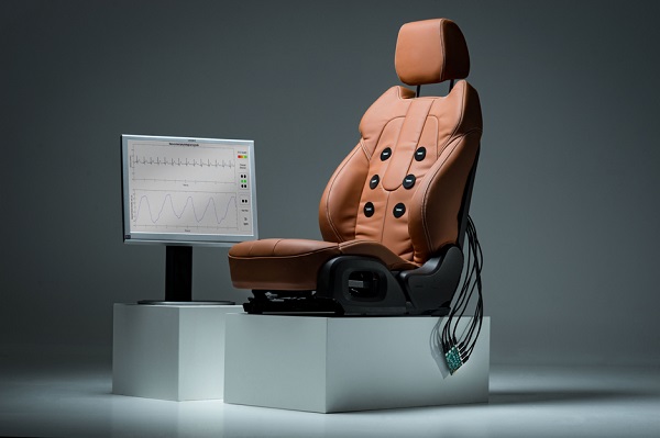
Okay, let’s take the example of a car: imagine that you could build sensors into the driver’s seat, steering wheel and dashboard so that your respiration rate, blood pressure, heart rate and cardiac activity could be measured on a continuous basis. First and foremost, a great many accidents could be prevented by detecting fatigue, stress or heart problems before they became an issue for the driver. And, in self-driving cars, these readings are essential, because the automatic pilot needs to be sure that it can rely on having an alert driver in certain situations. Then, in cases where an accident still can’t be avoided, these sensors could be used to check the condition of the driver and passengers and transmit their findings to the emergency services. Finally, your car seat could carry out your daily health check and send you a weekly report with all the facts and figures recorded about you.

Three ‘beyond wearables’ technologies

Imec is currently working on three technologies that will make this new ‘beyond wearables’ era possible: capacitive, radar and hyperspectral sensor technology.

1. Capacitive sensors

Imec researchers have integrated capacitive sensors into various places within an office chair and a car seat to carry out ECG readings and detect respiration rates through clothing. This principle is not new, but the technology has not been used before in practical applications because the quality of the readings becomes poor if the person moves about in their chair or if the car drives on a bumpy road. So it was a question of tackling the variable reliability that would make real-life applications possible.

The solution lay in the use of smart algorithms. First of all, algorithms can make adjustments/compensate for variations when movements and artifacts are detected, which makes the readings produced more reliable. Second, algorithms can make the system adaptive. This means that, in good conditions, an (ECG) signal of medical quality can be recorded. When conditions are not so good, the sensors switch to robust mode and take more general readings. For example, although you can still record the heart rate, obtaining an accurate ECG graph is not possible. This variable quality is factored into the readings and passed on as such – together with the results recorded.

2. Radar

Imec uses CMOS technology to produce compact and inexpensive radar modules. For example, imec’s 79GHz radar module can be used for car-to-car communication. But radar technology can also be used to measure heart and respiration rates. There are already radar devices on the market capable of measuring these parameters in one person standing still. However, imec researchers want to take things a step further and record readings from various people within a particular space, even if they are moving. Once again here you have to take variable quality of data into account.

Researchers have succeeded in using a 5-7 GHz radar device to measure the heart and breathing rates of two different people within a space, 2 meters away from the radar. As with capacitive sensors, smart algorithms are again used to tackle the issue of variable reliability so that this issue is not an obstacle for practical applications. The radar device used in this experiment is still fairly large and serves mainly to demonstrate the principle. Ultimately, a much smaller radar module needs to be used that can be integrated virtually invisibly into, say, an office environment or in the dashboard of a car. One radar module per space is sufficient to take readings from various people.

In parallel to this, researchers in the radar team are working on a new type of radar that operates at 140GHz. This unit is very compact because the antennas are very small and the whole system is integrated onto a single chip. This radar will enable both the distance and direction of a person to be measured in relation to the radar. This means that the readings for different people in the same space will become even more accurate.

3. Hyperspectral optical sensors

Hyperspectral cameras detect the reflected light of objects in very fine wavelength bands. These cameras can be used for applications such as checking the quality of foodstuffs, the composition of objects, etc. Imec is developing hyperspectral cameras based on CMOS technology. This will make them much more compact and cheaper than the types used today. It will also enable them to be used for a far broader range of applications.

With ordinary RGB cameras you can measure someone’s heart or respiration rate under certain conditions. With hyperspectral cameras you can do the same – but with much greater accuracy. You can do more things, too, such as measure the oxygen content in someone’s blood. This can be of value in hospitals or for baby monitoring at home, for example. There are already baby alarms that have an ordinary camera, but in the future – and for just a few euros more – it will be a hyperspectral camera.

Combining them for healthy driving or working, etc.

By combining the technologies described above – known as ‘sensor fusion’ – reliable readings can be achieved. For example, capacitive sensors can be used in a car seat to record ECG and respiration readings. But if the driver is wearing a thick sweater or jacket, this becomes more difficult. Then by integrating a radar device into the dashboard, to measure heart rate and respiration, it becomes possible to combine the readings and hence arrive at an end result that can be used in all circumstances. In an office environment, capacitive sensors can then be worked into an office chair, while a radar device or optical sensors can be placed in a laptop. In a living room, an armchair with capacitive sensors can be used in conjunction with a TV screen or light fixture with radar or optical sensors. Or capacitive sensors can be incorporated into the mattress of a (hospital) bed. Working with the manufacturers of these products, we are now looking to see how this technology for taking health readings can be put to further good use.

This also opens the door to new applications outside the hospital – for monitoring drivers or pilots, for example, or for use in at-home care situations for the early detection of heart problems that might save many people’s lives.

This research is part of the imec.iChange program, which is developing hardware and software for wearables and ‘beyond wearables’. One example of this is the MUSEIC chip family, developed by imec, and which is unique on account of its compactness, low energy consumption and low production cost. Developments at the moment are mainly for taking contact readings and are used in applications such as sticking plasters, bracelets and headsets. These chips are now being adapted to allow non-contact readings to be recorded.

Common headlight driver module with low EMI

0

Automobile LED headlight clusters combine high and low beams, daytime running lights, and sometimes signal and clearance lights into a single headlight cluster. The components of the cluster can have vastly different driver requirements, including voltage and current requirements, topologies, power levels or unique dimming functions.

Meeting the range of requirements usually means employing separate driver solutions. Using multiple drivers not only complicates BOMs and production; it can make it difficult to meet EMI standards. Each additional driver adds its high frequency signals to the EMI mix, complicating EMI qualification, troubleshooting and mitigation.

Although the headlight cluster for each automobile make and model may be outfitted with a creative variety of LED currents and voltages, they commonly top out at 30W total. With that in mind, there should be a number of drivers that satisfy the power and feature requirements of every string in the cluster.

There are not. Such a driver needs to take the relatively wide battery voltage range, and using a buck-boost topology, convert to the wide variety of string voltages. It needs to be small and versatile, to fit easily into the space constraints of the cluster, and produce little EMI, to minimize R&D efforts and eliminate the need for costly metal-shielded EMI cases. It should also be efficient. The Power by Linear LT8391A 2MHz buck-boost controller is unique in satisfying all of these requirements, making it possible to drive the entire headlight cluster, and more, with a single controller.

LT8391A 2MHz Synchronous Controller with Low EMI

The LT8391A is the first-of-its-kind 2MHz buck-boost controller for LED current regulation. The very high 2MHz switching speed enables the use of a single, small inductor and small overall solution size for high power LED applications. Unlike monolithic converters, whose power switches are contained within the IC package, controllers such as the LT8391A can drive external power switches with much higher peak currents, such as 10A.

Such peak currents would burn up the small IC packages of typical integrated converters. In contrast, a controller with external 3mm × 3mm synchronous MOSFETs can deliver much higher power. These MOSFETs can be arranged in tight quarters with hot-loop capacitors for very low EMI. The unique peak switch current sense amplifier architecture places the sense resistor next to the power inductor, which is outside of the critical input and output hot loops—reducing EMI. Optional spread spectrum frequency modulation (SSFM) further reduces the controller’s EMI.

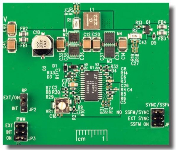
The 2MHz LT8391A 16V, 1.5A (24W) buck-boost LED driver in Figure 1 boasts as high as 93% efficiency with EMI filters and gate resistors as shown in Figure 2. Efficiency is 1%–2% higher with the optional EMI components removed. With small 3mm × 3mm MOSFETs and a single high power inductor, the temperature rise for this converter is low, even at 24W. At 12V input, no component rises more than 25ºC above room temperature. At 6V input, the hottest component rises less than 50ºC with a standard 4-layer PCB and no heat sink or airflow. It continues to run at full 24W load in the face of input transients down to 4.3V; or reduced load current via analog or PWM dimming when the input drops for long periods. The 8A–10A sense resistor makes this high power at low VIN possible.

The LT8391A includes the latest PWM dimming features and open LED fault protection. This synchronous buck-boost regulates current through a string of LEDs with a voltage that may or may not lie within the input voltage range, such as the 9V–16V car battery or a truck battery (18V–32V). It can run down to 4.0V cold crank input and can withstand up to 60V input transients. The LT8391A provides up to 2000:1 PWM dimming ratio at 120Hz and can use its internal PWM dimming generator for up to 128:1 accurate dimming ratio without the need for an externally supplied PWM clock.

CISPR 25 EMI for Automotive Applications

The 2MHz LT8391A LED driver in Figure 1 is designed for automotive headlights. It uses AEC-Q100 components and meets CISPR 25 Class 5 radiated EMI standards. Spread spectrum frequency modulation (SSFM) reduces EMI, and also runs flicker-free simultaneously with PWM dimming as shown in Figure 7. Its small size is highlighted by its small inductor and especially small input and output EMI filters. Large LC filters are not needed for 2MHz converters and only small ferrite beads are used for high frequency EMI reduction.

Automotive EMI requirements are not easily met by high power converters. High power switches and inductors, placed on large PCBs next to large capacitors can create undesirable hot loops, especially when a large sense resistor is included. The unique LT8391A buck-boost architecture removes the sense resistor from both the buck and boost switch-pair hot loops, enabling low EMI.

Figures 3 and 4 show measured EMI of the 24W LED driver of Figure 1. Despite this controller’s 2MHz operating frequency and 24W of power, this buck-boost passes CISPR 25 Class 5 radiated and conducted EMI. Class 5 is the most stringent requirement and the goal of most automotive EMI testing. Converters that cannot pass Class 5 EMI either get designed out of automotive circuits or must be encased in large metallic EMI shields. Even if the bulkiness of the shield does not create assembly issues, adding them is costly.

Buck-Boost for Multi-Beam Applications

LED headlight clusters can be both innovative and artistically creative. High beams and low beams can be wrapped up with nifty and distinctive daytime running lights (DRL). Because the daytime running lights are only needed when high and low beams are off, a single LED driver can be used to power either the high and low beam LEDs or the daytime running lights. This only works if the LED driver has a flexible input-to-output ratio and can both step-up and step-down the input-to-output voltage. A buck-boost design satisfies this requirement.

The multi-beam LT8391A buck-boost LED driver in Figure 5 can drive LED string voltages ranging from 3V to 34V. This enables it to drive both a low beam string and create a high beam by adding LEDs to the low beam string. The same driver switches over and drives a higher voltage, yet lower current, DRL. Switching from low-beam-only LEDs to a low/high beam combo string generates no spike on the output voltage or LED current as shown in Figure 6a. The LT8391A can transition between boost, 4-switch buck-boost, and buck regions of operation smoothly. Changing from a small number of LEDs to a high number of LEDs without an LED spike can be challenging for a converter, but this multi-beam circuit does this with ease. Switching back from high and low beams to just low beams is also very clean, without any harmful LED spikes.

The same is true when switching to and from the DRL string. Figure 6c demonstrates how the low beam is turned off and the DRL is smoothly connected to the output capacitor. Even the LED current is changed from 1A (high and low beams) to 700mA (8 LEDs DRL) without any issues. Other trim or signal LEDs can be added in as well, and the DRL can be blinked as a signal light. Figure 6d shows how the DRL can be PWM dimmed with the internally set PWM generator and then switched over smoothly to low beams when darkness falls.

FE and QFN Packages Fit Tight Spots

The LT8391A is available in a 4mm × 5mm 28-lead QFN for small size and a 28-lead TSSOP FE package for automotive designs. Both packages have thermally enhanced GND pads for power dissipation of the internal INTVCC LDO from higher voltages.

The internal LDO INTVCC regulator of these converters can handle driving four synchronous MOSFETs at 2MHz with about 15nC gate charge. The small size of the LT8391A FE 2MHz 16V, 1.5A demonstration circuit (DC2575A, based on the design of Figure 1) is shown in Figure 7. Only a single 5mm × 5mm inductor is necessary for this high power, versatile application.

Conclusion

The LT8391A 2MHz, 60V buck-boost LED driver controller powers LED strings in automotive headlights. Its features include its low EMI 4-switch architecture and spread spectrum frequency modulation for meeting CISPR 25 Class 5 EMI requirements. The unique, high switching frequency allows it to operate above the AM band, requiring very little EMI filtering. Its small size and versatility enable use in headlight cluster LED strings of a variety of voltages and currents.


Why you should change your oil

0

Oil acts as an essential lubricant that eliminates friction between your pistons and the piston housing. Failure to get your oil changed on time leads to low oil levels and dirty oil, which leads to consequences like:

  • Overheating
  • Lower efficiency
  • Lower performance
  • Shorter engine life
  • Engine failure

Neglecting oil changes can decrease how many miles you car can go over its lifespan as well as its value should you try and sell it at some point. Keeping up with oil changes helps ensure your car stays healthy regardless of how many miles are on it.

HOW MANY MILES CAN YOU GO WITHOUT AN OIL CHANGE?

The rule of thumb used to be that you should get your oil changed every three months or 3,000 miles, whichever comes first. However, vehicles are built differently these days, which means that you can generally go longer between oil changes.

HOW OFTEN SHOULD YOU CHANGE YOUR OIL?

The recommended length of time between oil changes varies significantly between different makes, models, and years. Some models still require an oil change every three months or 3,000 miles, while others can go for five months or 5,000 miles. Still other vehicles are able to go as long as 15,000 miles between oil changes. In order to tell if it’s time for an oil change, we recommend that you:

    • Check your owner’s manual for recommended oil change intervals
    • Use the dipstick to see if your engine oil is at the recommended level
    • Check to see if your engine oil is dirty
    • Follow prompts from oil change warning lights

Italian truck maker opens showroom in Nairobi

0

The opening of the showroom located on the ICD Road, adjacent to Mombasa road, comes after the company opened an plant in Mombasa that will assemble about 300 trucks per year and about 5,000 units in 5 years time.

IVECO and GMC plans to start production of the new Stralis X-Way truck designed for construction logistics, at the Mombasa assembly plant later in the year.

“We chose Kenya for our investment because it is one of the most advanced countries in Africa and the services that we need for the trucks such as maintenance and asset financing are available here,” said Marco Torta, Area Manager for East Africa during the opening of the ceremony.

Torta said the showroom has been designed to provide customers with Sales, Service and Spare Part services.

GMC was appointed as IVECO’s dealer in Kenya in 2017 and assembles the Eurocargo medium truck and the Trakker heavy tipper version at its assembly plant in Mombasa.

How to rotate your tires


Tires are expensive. You want to make them last as long as possible. To do that, you need to rotate your tires every once in a while (different guidelines range from 3,000 miles to 8,000 miles).

Why is this so important? No matter what kind of car you drive, the tires at each corner are all doing a slightly different job, which means they wear differently. Front-wheel-drive cars in particular make their front tires work a lot harder than the rears—the front pair bears all the burden for accelerating and turning, and most of it for braking. In addition, front-wheel cars carry most of their weight on the front end.

But you’re not off the hook if you drive a rear- or all-wheel-drive vehicle. Any car will wear its tires in different ways just because of the peculiarities of that particular car’s suspension or alignment. So you want to rotate them if you can.

The Most Important Step: Making Sure You Can Rotate

Don’t skip this step! The first thing you need to do is figure out whether your car’s tires can be rotated at all. Many performance cars use staggered sizes, which usually means the rear tires are wider than the fronts (though not always, as demonstrated by the wider front tires on the Audi RS3). In this case, you can’t slap your wide rear tires on the front.

Performance cars also sometimes use directional tires, meaning the tread pattern is designed to work in one direction (denoted by an arrow on the sidewall, or more generally by a V-shaped tread pattern). You can’t swap these tires side to side at the front or rear end, since changing sides would flip the tread pattern in the wrong direction.

image

A Goodyear Eagle F1—a directional tire

One more variable: wheel offset, which means how “deep” your wheels are relative to the car’s body. Some cars might have the same size tires on all four corners, but different wheels. For example: If you’re lucky enough to own a 2014 Chevrolet Camaro z/28, the tires are all the same size but you’ll have to take them off the wheels to rotate them, because the rear wheels are wider than the fronts. Check your owner’s manual on that one, since it won’t be obvious just by looking.

How to Rotate Your Tires

image

Got a full-size spare on a matching wheel? Showoff. But you can put that in the mix when you rotate tires, too.

If all your tires and wheels are the same size and non directional: You can swap diagonally front to rear, or move the fronts to the rear diagonal corner while moving the rears forward on the same side. If you have a full-size spare on a matching wheel, you can get really anal retentive and add that to the mix, too.

If you’ve got non-staggered directional tires: Move the rears to the front and vice versa on the same side of the car. With non directional staggered sizes, you can just trade sides at the front and rear.

How to fix squeaky brakes


Squeaky brakes are a serious automotive annoyance. But are squeaking brakes dangerous? How much does it cost to fix them? We’ve got your answers right here.

What Causes Breaks to Squeak?

Don’t expect brakes to be totally quiet sometimes, they’re going to make some noises. Don’t panic, because a squeaky brake can stop a car just like a silent one can.

What causes the squeal? Modern brakes use a cast-iron disc squeezed between two brake pads lined with friction material. Under the right conditions, the disc, the pads and the caliper they’re mounted in can start to vibrate in exactly the same way a violin’s string vibrates when stroked by the horsehairs on the bow. Most brake squeals occur at a single discrete frequency. The speed of the vehicle and how hard you press down on the left pedal will only change the volume of noise, because the pitch is controlled by the stiffness and mass of the pad and disc.

Inadequate development at the manufacturer that leaves brake systems prone to noise can usually be overcome by a Saturday mechanic without totally re-engineering the caliper/mount/pad/disc system. We can try to damp out the noise, or simply change the resonant frequency of the whole arrangement until it stops singing in any audible frequency.

Here’s how.

Normal Brake Pad Noises

Many brake pad compositions will make a swishing or grinding noise for the first few stops in the morning until the pads warm up and drive off any moisture they’ve accumulated overnight. Ever notice a hissing or grinding noise on some rainy or dewy mornings? It’s the pads sweeping a thin film of rust that’s formed on the iron discs, and it’s perfectly normal.

In the past, brake pad friction material relied heavily on asbestos. Unfortunately, asbestos tended to give asbestos workers and brake mechanics lung cancer, so the industry has almost completely changed over to less dangerous alternatives. Kevlar is one material that’s seen a lot of use, but it tends to be dusty. Improved brake performance is more important nowadays because of increased safety requirements and equipment—and the extra road-hugging weight that comes along with these. That leads to the increased use of metallics and ceramics in the brake pad friction material. And this stuff can make the brakes hiss or even grind a little as you slow down. It’s a small price to pay for increased performance. So all pad noise is fine, right? Hold up there, Sparky, there’s one brake noise you need to pay attention to right away.

Many brake pads have a small finger of spring steel that will scrape on the disc as the pad reaches its wear limit. This tells you that it’s time to change pads for fresh, thicker ones before the friction material wears completely away, and you’re trying to slow down on the metal backing plates. It’s a sound not easily confused with brake squeal—it’s more of a ripping-sheet-metal noise, not a single, high-pitched note.

Stop the Squeak
red brake
Okay, let’s dig in and silence our brake noise. One fix is to simply change pads to a different type of friction material. It’s usually hard to beat the original-equipment pads for a good compromise of pad life, noise, grip, dust creation and price, but changing to an aftermarket premium metallic or ceramic pad just might change the interaction that affects the resonant frequency of the pad and disc and, literally, change its tune.

Go into any auto parts store and you’ll see a shelf full of potions and widgets claiming to cure squeaks. One class of products I’m leery of is simple aerosols that you spray onto the pad’s friction material. I have no idea if they actually make the squeak go away, because I’m unwilling to try anything that changes the friction characteristics of the pad. Let’s not forget, the first reason your brake system exists is, in fact, to make your car slow down. Anything that could reduce that system’s effectiveness in any way is probably not a good idea.

Still got noise? Or still have plenty of pad material remaining and don’t want to drop fifty or a hundred bucks on a fresh set? You may be able to decouple the piston acoustically from the pad by purchasing shims made of Teflon, which are intended to go between the pad and the caliper’s hydraulic piston. I’ve tried those shims with middling success—sometimes they work and sometimes they don’t. Warning: Some calipers will not have enough extra travel in the piston bore to allow any shimming without making the brakes drag, at least with fresh, unworn pads.

You can achieve a similar decoupling without Teflon shims by simply coating the back face of the pad’s backing plates with high-temp brake grease or even anti-seize compound. Unlike shims, this tweak won’t last forever, as water and road dirt will wash it away eventually.

We chose high-end ceramic-based pads for our brake job, hoping the different friction characteristics would cure the squeal. Surprise, the new pads came out of the box fitted with Teflon-coated shims already installed.

A Sticky Solution

The favorite tweak for squeaks relies on a different principle: Instead of using shims or lubricants to decouple the pad from the caliper, stick the backing plate to the piston or caliper housing, effectively making its mass far larger. That will move the system’s resonant frequency out of the range that squeals. A smear of Super Glue won’t do it: You need something that will withstand the water, salt, filth and especially the heat that cars see in hard everyday use. How hot do brake systems get? I’ve seen brake discs glowing bright orange at the bottom of Pikes Peak, and flames shooting out of the brake drums of trucks descending Donner Pass. I’ve seen the brakes on my own race car visibly glow right after a few hot laps.

I’ve used several products over the years, but they’re all basically anaerobic adhesives, applied as either a lipstick-style film or a toothpaste-style goo. The application of this product is simple: Remove and clean up the old pads, or use new pads. Clean the area on the piston and caliper where the pad backing plate touches. Apply the anti-squeal adhesive, reinstall the pads and button up. These anaerobic products will stay gummy until you apply the brakes and squeeze out the oxygen. Then they stick like, well, glue.

Whenever you’re installing any brake parts, be sure you remove any corrosion or road dirt from the mating parts—the brake pad or caliper housing needs to be able to slide in and out to compensate for wear. Clean up any sliding parts, which may require a wire brush or a file, until you can push the pads in and out with your bare hands. I prefer to replace any brake hardware (especially on drum brakes) that isn’t in perfect condition—hey, it’s cheap insurance. Apply a thin film of high-temp brake grease to any sliding surfaces. Obviously, avoid getting anything like grease or anti-seize on the pad or disc, and clean any greasy handprints off the disc surface before you hang the wheel on too.

Dealer to launch showroom for BMW in Nairobi

0

Inchcape Plc, a UK-based luxury car dealer has plans to set up Kenya’s first BMW-dedicated showroom in Nairobi, upping competition for high-end vehicles.

The firm, which took over the BMW franchise from Simba Corporation beginning January, says it is setting up a double-storey showroom for the German car brand at Westlands Delta Corner.

Inchcape Kenya marketing manager Charity Mutunga said that on completion, the showroom is expected to give the firm sufficient space to display extensively. “Having taken BMW dealership as from January 2019, the new facility will offer our customers a bespoke showroom experience to view and interact with our range of exceptional BMW models,” said Ms Mutunga.

“We want to serve BMW customers better and then ensure we give our premium customers a truly premium experience, including after-sales service,” she added.

This will be a change in strategy given that its predecessor was offering sales and service for BMW along that of other brands in one location. Currently, Inchcape relies on a shared service centre for BMW and Jaguar land rover at Nairobi’s Enterprise Road.

Kenya is Inchcape’s second market in Africa after Ethiopia where it deals in several brands, including Toyota and Hino. The multinational sells several vehicle brands like Mercedes Benz, Toyota, Audi and BMW in 31 countries.

As at the end of June last year, sales of BMW, Jaguar and Land Rover models stood at 74 units or 54% of the total 137 sold in the industry. Change in local car dealership has been rising in the recent past where automakers are constantly reviewing their franchises.

DT Dobie took over the Volkswagen dealership from CMC even as it lost Nissan franchise to Crown Motors while GM terminated Isuzu EA’s sale of Chevrolet cars.

How to adjust your headlights


It’s important to have quality headlights to light your path. But those bulbs aren’t doing any good if they’re not correctly aimed at the road, and that’s something many owners forget or downright neglect when owning a car.

Time can lead to a car’s headlights becoming misaligned as can frequently replacing the bulb. This could lead to reduced visibility, which is essential when driving at night. When you’re traveling at 60 miles per hour, you have mere seconds to avoid a collision if something darts into the road. Misaligned lights can reduce reaction time to zero.

Making Some Adjustments

Adjusting headlights is an easy though often tedious task that takes time to get right, and every car is different. But with practice and patience, you can learn to do it in your driveway in a matter of minutes.

Start by checking whether your car has built-in bubble levels meant to help you align the headlights. Honda, for example, offers vertical and horizontal bubble levels that make it easy to tell if your headlight aim is off. They’re often located on the top and side of the headlight unit. With these, you can tweak the aim (as explained below), until the bubble is centered in the level. Some makes and models offer just vertical or horizontal bubble levels while most others provide no visible alignment indicator at all.

MISALIGNED LIGHTS CAN REDUCE REACTION TIME TO ZERO.

If your car lacks such convenience, don’t worry. There’s a surefire DIY way to check your headlight alignment and get your lights back into shape.

First, park on flat ground and make sure your car is level. That means unloading heavy stuff from the trunk, filling the gas tank to full, and making sure tire pressure is correct at all four corners. You can’t align headlights if your car isn’t level. Check the suspension, too.

Second, you’ll need a plain wall. Pull the car as close the wall as possible and turn on your lights. This way, you’ll find the centers of the low-beam headlights. Mark both spots with a single piece of horizontal tape running through the middle. Make the vertical tape marker about two feet long, again running through the center of the low-beams.

Next, find the adjusters, which are often located somewhere on the headlight housing. Each make and model is different, but generally the adjusters are a type of screw or bolt on the back and side of the headlight unit. While they’re not often marked, they are often gray or silver, which stands out from the black headlight backs.

However, some vertical adjusters are located on the bottom of the unit (like several GM vehicles), which makes access difficult. Sometimes, automakers cut a hole in the vehicle’s frame that allows access to the adjusters. A look at the owner’s manual or a quick Google search can help.

If you follow these guidelines, you’ll give yourself the best chance possible to avoid some unwelcome surprises on your next road trip.

- Advertisement -