Sunday, May 31, 2026
Home Blog Page 85

2020 Nissan Versa Sedan puts a new face on cheap basic transportation


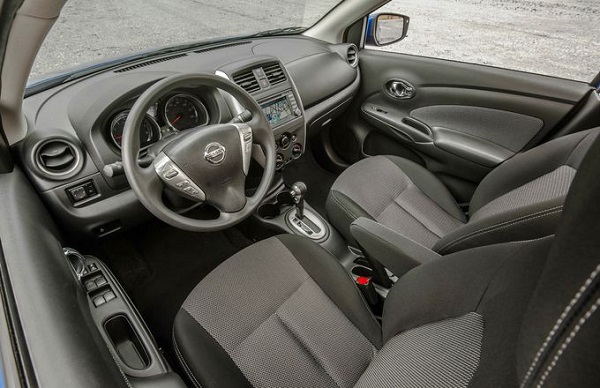
Nissan knows cheap: its Versa subcompact sedan has been the least expensive car on the market for some time now, and there’s now a new Versa on the horizon, as shown in these spy photos. With considerably more attractive proportions than the current car, this new model looks to be far less gawky, although its core mission to provide inexpensive, efficient basic transportation isn’t likely to change much.

From what we can see, the Versa will adopt styling cues from its sedan big siblings, the Altima and Maxima. The vague outline of Nissan’s V-Motion grille design is visible through the camouflage, while the taillights are shaped similarly to the Altima’s. A more tapered roofline and a higher decklid avoid the awkwardly tall silhouette of the current Versa sedan. We don’t expect much of a change in size, and we’re sure Nissan will attempt to maintain the current car’s surprisingly large amount of rear-seat space.

When it arrives later this year, the new 2020 Versa sedan will compete against familiar suspects including the Toyota Yaris sedan, the Chevrolet Sonic, the Hyundai Accent, and the Kia Rio. A redesigned version of its hatchback stablemate, the Versa Note, should arrive within the next year as well.

Have a glimpse on the New 2020 Toyota Corolla Sedan


As the Toyota Corolla‘s styling has gotten more and more extreme over the years, its lack of driving character has become more and more glaring in contrast. The newest iteration of the venerable compact car, the 2020 Corolla sedan, is here with the intention to change that. With the same power train and underpinnings that pleased us in the new Corolla hatchback, and significantly more attractive styling, this sedan is shaping up to be the first desirable and competitive Corolla in quite some time.

This 12th-generation lineup is also the first truly “new” Corolla in a while. Although the last few generations have used mostly carryover platforms, this Corolla is truly novel underneath, riding on a platform that fits under the Toyota New Global Architecture (TNGA) umbrella. Its wheelbase is the same as before, but the track is wider and the suspension arrangement is new and significantly more sophisticated. The independent multilink setup in the rear that replaces the previous sedan’s torsion beam aims to provide much improved ride quality and handling.


L, LE, and XLE versions of the new Corolla sedan use a carryover 1.8-liter four-cylinder that makes 139 horsepower and 126 lb-ft of torque. But the more interesting story under the hood is the optional 2.0-liter four-cylinder that ups output significantly to 169 hp and 151 lb-ft of torque. It’ll be in the Corolla’s sportier SE and XSE trim levels, which also get visual tweaks including a different front grille and larger 18-inch wheels. A continuously variable automatic transmission (CVT) will be standard, with a six-speed manual transmission with rev-matching capability available on the SE with the 2.0-liter engine.


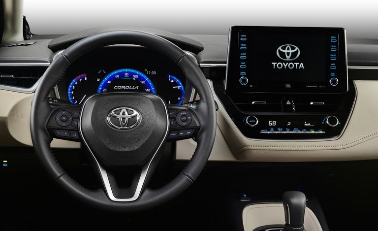
Inside, the Corolla sedan’s cabin mostly mimics the Corolla hatchback’s, which is a good thing given that car’s uptick in material quality and design. The base L model has a 7.0-inch touchscreen display, but all other trims get an 8.0-inch touchscreen with Toyota’s Entune infotainment system that includes Apple CarPlay (Android Auto is not on the menu, unfortunately). Two-tone leather upholstery will be optional, as pictured here, with a few different color combinations.

As with the outgoing Corolla, several active-safety features standard across the lineup, including adaptive cruise control, forward-collision warning, lane-keeping assist, and automated emergency braking. Blind-spot monitoring will be optional.

Expect pricing to mostly hold the line compared to today’s Corolla, with the base L starting around $20,000 and better-equipped trim levels pushing past $25,000. It will start arriving at dealerships in spring 2019.

Common sense about safe driving

0

If you’re in an accident, first make sure no one in the car is injured. Next, check on the passengers in the other vehicle, pedestrians and anyone else nearby to make sure they’re OK. Then do these five things:

Stay at the scene

Leaving can result in legal consequences, like fines or additional violations.

Call 911 or the local police immediately

They’ll dispatch an officer and medical personnel to the scene of the accident. Once the cops arrive, wait for them to complete an accident report.

Stay in the car

If you’re on a busy highway, stay inside the car and wait for the police or an ambulance. It’s dangerous if passengers stand along a freeway or other road with lots of traffic.

Stay calm

Don’t get into an argument or a fight with the other driver. Simply exchange contact and insurance information. If possible, also get the name and phone numbers of witnesses.

Contact your insurance provider

Call your insurance provider to report the claim. Your agent will ask you for any paperwork you receive about the accident, and will give you important information on getting your car fixed.


What to do when pulled over

0

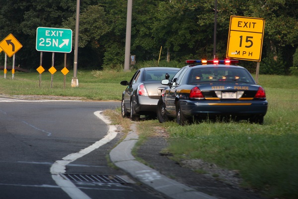
If you notice that a police car is following you with the lights flashing, pull over to the side of the road safely and quickly. Wait inside your car for the officer to approach, and be prepared to:

Turn on the light

Turn on your interior light at night and keep your hands where the officer can see them, preferably on the steering wheel.

Keep your hands visible

Don’t reach under your seat or into your glove box. This may cause the officer to think you’re reaching for a weapon or hiding something.

Provide necessary documentation

Give your license and proof of insurance to the officer if asked. If the officer asks you to step out of your car, do so without sudden or threatening movements.

Be polite

Stay calm − don’t become argumentative, disorderly or abusive − and never attempt to bribe the officer.

If a citation is issued, present your story in traffic court if you feel you’ve been unfairly treated. You may be represented by a lawyer and, if necessary, you’ll be heard by a judge or magistrate.

Driving Safety Tips Every Driver Should Know

0

When you’re behind the wheel of a car whether alone or with passengers – driving safely should always be your top concern. We’re more distracted than ever, so it’s crucial to know the basics of safe driving and practice them every time you’re on the road. Here are some driving safety tips:

Top 4 driving safety tips

Focus on driving

  • Keep 100% of your attention on driving at all times – no multi-tasking.
  • Don’t use your phone or any other electronic device while driving.
  • Slow down. Speeding gives you less time to react and increases the severity of an accident.

Drive “defensively”

  • Be aware of what other drivers around you are doing, and expect the unexpected.
  • Assume other motorists will do something crazy, and always be prepared to avoid it.
  • Keep a 2-second cushion between you and the car in front of you.
  • Make that 4 seconds if the weather is bad.

Also Read: Preventing Future Accidents: Tips for Safer Driving and Vehicle Maintenance

Make a safe driving plan

  • Build time into your trip schedule to stop for food, rest breaks, phone calls or other business.
  • Adjust your seat, mirrors and climate controls before putting the car in gear.
  • Pull over to eat or drink. It takes only a few minutes.

Also Read: Drive Safe, Save Money – Proven Vehicle Maintenance Tips for Long-Term Durability

Practice safety

  • Secure cargo that may move around while the vehicle is in motion.
  • Don’t attempt to retrieve items that fall to the floor.
  • Have items needed within easy reach – such as toll fees, toll cards and garage passes.
  • Always wear your seat belt and drive sober and drug-free.
  • Don’t allow children to fight or climb around in your car – they should be buckled in their seats at all times. Too much noise can easily distract you from focus on the road.
  • Avoid driving when you’re tired. Be aware that some medications cause drowsiness and make operating a vehicle very dangerous. Learn more about drowsy driving.
  • Always use caution when changing lanes. Cutting in front of someone, changing lanes too fast or not using your signals may cause an accident or upset other drivers.
  • Be extra careful while driving during deer season.

Volvo puts drunk drivers on notice

0

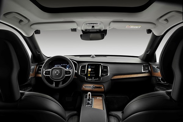
Volvo will add sensors to detect drunk drivers and distracted drivers, announcing all vehicles on the SPA2 platform will be fitted with advanced driver monitoring technology from the early 2020s.

Subaru already has a driver-monitoring camera in the Forester, designed to force owners who take their eyes off the road to pay attention, but Volvo is promising to take things a step further, by using the semi-autonomous systems in its vehicles to take control.

The move is a response to figures from the American NHTSA, revealing almost 30 per cent of traffic fatalities involved drunk or drugged drivers in 2017.

When the cars detect an impaired driver, they could limit their top speed, alert Volvo on-call assistance and, if all else fails, take over and park the car on the side of the road.

As for how the system will know when you’re too drunk to be driving? A lack of steering input, having your eyes closed (or off the road) for extended periods of time, and extreme weaving across lanes are all telltale signs, along with significantly delayed reactions.

These behaviours are also consistent with people distracted by their phones.

“There are many accidents that occur as a result of intoxicated drivers,” said Trent Victor, professor of driver behaviour at Volvo Cars.

“Some people still believe that they can drive after having had a drink, and that this will not affect their capabilities. We want to ensure that people are not put in danger as a result of intoxication.”

The news comes just weeks after Volvo announced it’ll limit the top speed on its cars to 180km/h, as it pushes to have no-one die in its cars.

According to the company, the move is designed to start a conversation about whether carmakers have an obligation to install technology “that changes their driver’s behaviour, to tackle things like speeding, intoxication or distraction”.

Hyundai joins automotive Grade Linux

0

Automotive Grade Linux, a collaborative cross-industry effort developing an open platform for the connected car, has announced that Hyundai has joined Automotive Grade Linux (AGL) and the Linux Foundation, the nonprofit organization enabling mass innovation through open source.

“Hyundai has been active in open source for years, and their experience will benefit the entire AGL community,” said Dan Cauchy, Executive Director of Automotive Grade Linux at the Linux Foundation.

“This is a significant milestone for us, as the rapid growth of AGL proves that automakers are realizing the business value that open source and shared software development can provide. We look forward to working with Hyundai as we continue on our path to develop open source solutions for all in-vehicle technology.”

AGL is an open source project at the Linux Foundation that is changing the way automotive manufacturers build software. More than 140 members are working together to develop a common platform that can serve as the de facto industry standard. Adopting an open platform across the industry enables automakers and suppliers to share and reuse the same code base, which reduces development costs, decreases time-to-market for new products and reduces fragmentation across the industry.

“Open collaboration is essential as we realize our connected car vision,” said Paul Choo, Vice President and Head of Infotainment Technology Center at Hyundai Motor Company. “AGL has built a robust platform that offers the flexibility to design and build new services on top of it, and quickly bring them to market. We look forward to working with the community to expand the platform and collaboratively develop the underlying technologies that are vital to the next generation of connected vehicles.”

 Developed through a joint effort by dozens of member companies, the AGL Unified Code Base (UCB) platform is an open source software platform for infotainment, telematics and instrument cluster applications. It provides 70% of the starting point for a production project and includes an operating system, middleware and application framework. Automakers and suppliers can customize the platform with features, services and branding to meet their unique product and customer needs.

AGL at CES 2019
The AGL Unified Code Base (UCB) platform, a CES 2019 Innovation Awards Honoree, will be on display in the AGL booth at CES 2019 in the Westgate Hotel Pavilion, 1614.

The AGL booth will feature demonstrations of open source technology from AGL members AISIN AW, Audiokinetic, Cognomotiv, DENSO, DENSO TEN, EPAM Systems, Fiberdyne Systems, ForgeRock, Igalia, LG Silicon Valley Lab, Microchip, NTT DATA MSE, Panasonic, Renesas, SafeRide Technologies, Tuxera and VNC Automotive.

The booth will be open to the public during CES show hours from January 8-11, 2019. To request a meeting or experience a demo at CES, please visit https://www.automotivelinux.org/book-a-demo.

Fingerprint sensing in the car: a security or convenience or both


Now the automotive industry is looking to another feature of the smartphone’s user interface, the fingerprint sensor, to enhance and modernise the driver’s interface to functions in and even beyond the car. In fact this – and other forms of biometric authentication – appear to show great promise if implemented with sensitivity to user privacy and the limitations of the automotive operating environment. But the use cases of biometric authentication in the car look set to differ, perhaps surprisingly, from those of the smartphone.

Personalising the user experience

The obvious assumption about fingerprint sensing in the car is that it should be used as a convenient and secure replacement for the key both for providing access to the cabin and for starting the engine. In the smartphone, of course, fingerprint sensing performs this security function, barring access to any person other than the registered owner. In a car, however, fingerprint sensing is an unsatisfactory form of security in vehicles for two reasons.

The first is because of a difference in the usage model of a car from that of a smartphone. A car may be driven by people other than its registered owner. For instance, users of a valet parking service need to give the valet a means of starting the car. Equally, a driver who finds himself or herself incapacitated might want a suitably insured person to drive the vehicle on their behalf. A fingerprint sensor, then, can never entirely replace a key.

There is a security as well as a convenience reason why a fingerprint sensor cannot be the sole means of securing the car. This is because every fingerprint sensing technology in existence has a ‘false acceptance rate’. Occasionally, every fingerprint sensor will wrongly identify a stranger’s fingerprint as that of the registered user. Even the smallest risk that a potential car thief could steal this expensive asset simply by pressing a fingerprint sensor is too great for car manufacturers to accept. For security reasons, therefore, fingerprint sensing would always need to be backed by a supplementary form of access control. Conventional RF-operated keys, then, are not about to be superseded by fingerprint sensors on the door handle or Start button.

Fingerprint sensing does, however, enable two far-reaching improvements to the driver’s user experience: personalization, and payment authentication.

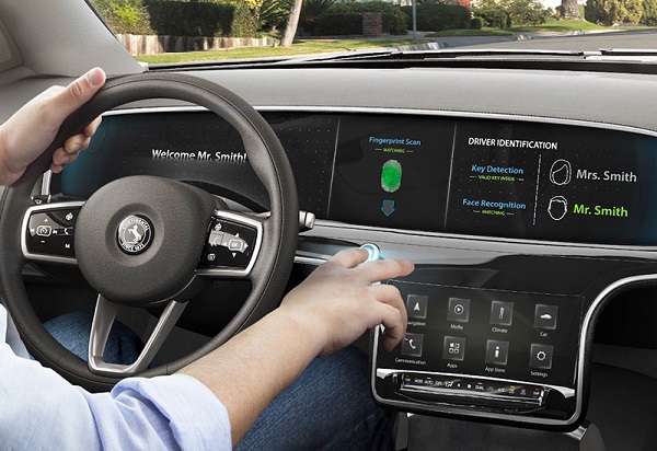
In a car with two or more regular drivers, the fingerprint sensor may identify who is driving, allowing the car’s operations to be configured to that driver’s preferred settings. This affects convenience settings such as the position and height of the driver’s seat, mirrors and steering wheel, comfort settings such as the temperature and direction of the cabin air stream and vents, and entertainment settings, such as Bluetooth pairing with the driver’s phone, the choice of favorite radio stations, the sound balance in the audio system, and even the appearance and menu configuration of the CID.

Personalization of the user interface strengthens the emotional bond between owners and their vehicle, making it uniquely theirs. In an important way it also improves the driver’s ability to make use of the sophisticated features and functions in a car, many of which in today’s cars are hidden behind multi-layered menu structures and complex sets of commands. Research has shown that for every step added to a user interface, 10% of the users drop out. Personalization via a fingerprint sensor reduces the number of steps to one or even none for many aspects of the user interface, thus making valuable features much more readily accessible to users.

In-car fingerprint sensors can also dramatically improve the user’s experience of making payments inside the car, for instance when paying road tolls and parking fees, or to charge a payment card at a drive-through store.

At a parking garage, for example, a number plate recognition system would automatically identify the car, and a payments back end would link the car to a pre-registered payment card. The payment terminal would then send a payment authorisation request wirelessly to the car. The driver would authenticate the use of the payment card to pay the parking fee by pressing the fingerprint sensor.

Standards such as the UAF specification published by the FIDO Alliance (fidoalliance.org) define processes for acknowledging biometric indicators such as fingerprints as an alternative to passwords or PINs. Authentication by fingerprint is a far quicker and easier operation than leaning through the driver’s door window to insert a card in a reader and then enter a PIN on a keypad.

Biometric indicators: which will the car industry favor?

Various forms of biometric sensing are under consideration by the car industry, including facial recognition, iris recognition and heart-rate variability (a parameter which may be measured by a wireless health-monitoring wristband) as well as fingerprint sensing. Looking into the future, there is some interest in the potential to use biometric indicators such as heart rate, blood pressure and sweat to make a reading of the driver’s state of health and state of mind. This might allow the car to issue an alert to the driver, for instance to park the car and rest if the indicators suggest that the driver is drowsy.  With the advent of advanced driver assistance systems (ADAS), the car may even take over control from the driver and park itself in a safe place.

Today, however, the industry’s preferred biometric indicator is the fingerprint. This is because the operation of fingerprint sensors is well understood by users, and because the technology of fingerprint sensing has been proven in the mobile device industry.

There are in fact three fingerprint sensing technologies available to car manufacturers today:

  • Capacitive fingerprint sensing is the technology used in the world’s best-selling smartphones, in which its ultra-small size – a sensing pad just a few tens of microns thick and a small controller IC – and low power usage are extremely attractive. In a small number of cases, capacitive fingerprint sensing might fail because of ‘dry finger’ problems, or when the user has severe scarring or calluses.
  • Optical fingerprint sensing is familiar to travellers who have crossed the US border, where an image of a fingerprint is captured and linked to passport information. An optical sensor is highly reliable and accurate, but the sensors require a backlight to illuminate the finger, and are still comparatively bulky compared to capacitive solutions.
  • Ultrasonic sensing offers reliable detection of fingerprints in 3D, but has not found its way into mainstream mobile devices. It is today an expensive and relatively unproven option.

The benefits of capacitive fingerprint sensing that appeal to smartphone makers appeal equally to the car industry. In particular, the ultra-thin sensing pad gives car designers the total freedom they want to design the styling, shape and configuration of the sensor unit to suit the form and functions of the cabin.

Prototypes and demonstrations developed by Synaptics show how a fingerprint sensor may be integrated smoothly into the normal design of a car’s interior without requiring additional surface space, and without cluttering the design of the cabin. Fingerprint sensors may readily be integrated, for example, into a touch-sensing directional pad mounted on the steering wheel.

This space-saving design allows the fingerprint sensor to be used with both the driver’s hands on the steering wheel. In the Synaptics demonstration, the fingerprint sensor is combined with a force sensor also integrated into the sensing pad. This means that an authentication event may be triggered only when the pad is pressed, eliminating the risk that the driver could inadvertently authenticate a payment, for instance, when resting the hands naturally on the steering wheel.

Requirements for a successful implementation

There are three elements to a successful fingerprint sensing implementation. The mechanical design of the sensing pad, the sensitivity of the controller IC, and the algorithms running on the IC for accepting or rejecting fingerprints.

The sensing controller IC and the software it runs may be sourced from third-party suppliers such as Synaptics. Synaptics has the advantage that its automotive fingerprint sensor solutions draw on technology shipped in tens of millions of smartphones worldwide. The learning and development baked into this technology ensure that automotive implementations can achieve just as high a performance as implementations in the mobile phone.

The mechanical design – the area and thickness of the sensing pad, the material it is made of, and its positioning in the vehicle – will be decided by the car manufacturer. Here, OEMs may draw on the experience that Synaptics has had in the smartphone market: smartphone manufacturers have experimented with many different configurations of the sensing pad, for instance. Some have worked, some have not: knowledge of previous design iterations will allow automotive manufacturers to complete sensor designs faster and avoid experimenting with design configurations that are known not to work.

As a proven technology, then, the capacitive method is set to be the first technology for fingerprint sensing to be adopted in the car. Time will tell whether it turns out to be preferred by the automotive industry in the longer term, and no doubt optical, ultrasonic and other technologies will be evaluated, and other forms of biometric sensing may be introduced.

Today, however, capacitive fingerprint sensing is both liked and understood by users of smartphones, and it provides a ready-made way for car manufacturers to make their users’ experience of their products more convenient, more personal and more secure.


Functional safety for integrated circuits

0

Typically, integrated circuits are developed to either IEC 61508 or ISO 26262. In addition, there are sometimes additional requirements in the level two and level three standards. Developing and assessment to the functional safety standards are what give the confidence that these sometimes complex integrated circuits are sufficiently safe. When IEC 61508 was written it was targeted at bespoke systems, as opposed to open market mass produced integrated circuits.

This article will review and comment on the known functional safety requirements for integrated circuits. While the article concentrates on IEC 61508 and its application in industrial sectors, much of the material is relevant to applications such as automotive, avionics, and medical.

Functional Safety

Functional safety is the part of safety that deals with confidence that a system will carry out its safety related task when required to do so. Functional safety is different from other passive forms of safety such as electrical safety, mechanical safety, or intrinsic safety.

Functional safety is an active form of safety; for example, it gives confidence that a motor will shut down quickly enough to prevent harm to an operator who opens a guard door or that a robot will operate at a reduced speed and force when a human is nearby.

Standards

The key functional safety standard is IEC 61508.1 The first revision of this standard was published in 1998 with revision two published in 2010 and work beginning in 2017 to update to revision three with a probable completion date of 2022. Since the first edition of IEC 61508 was published in 1998, the basic IEC 61508 standard has been adapted to suit fields such as automotive (ISO 26262), process control (IEC 61511), PLC (IEC 61131-6), IEC 62061(machinery), variable speed drives (IEC 61800-5-2), and many other areas. These other standards help interpret the very broad scope of IEC 61508 for these more limited fields.

Some functional safety standards such as ISO 13849 and D0-178/D0-254 have not been derived from IEC 61508. Nevertheless, anybody familiar with IEC 61508 and reading these standards would not be too surprised by the contents.

Within a safety system, it is the safety functions that perform the key functional safety activities when the system is running. A safety function defines an operation that must be carried out to achieve or maintain safety. A typical safety function contains an input subsystem, a logic subsystem, and an output subsystem. Typically, this means that a potentially unsafe state is sensed, and something makes a decision on the sensed values and, if deemed potentially hazardous, instructs an output subsystem to take the system to a defined safe state.

It is rather reserved for applications like nuclear and rail where hundreds or even thousands of people can be hurt. There are also other functional safety standards such as automotive, which uses ASIL (automotive safety integrity levels) A, B, C, and D and ISO 13849. Its performance levels a, b, c, d, and e can be mapped to the SIL 1 to SIL 3 scale.

The author is not convinced that a claim of greater than SIL 3 is possible for a single IC. However, it is noted that the tables in Annex F of IEC 61508-2:2010 show a SIL 4 column.

Requirement 3—Be Fault Tolerant

No matter how reliable the product, bad things will sometimes still happen. Fault tolerance accepts this reality and then addresses it. Fault tolerance has two main elements. One is the use of redundancy and the other is the use of diagnostics. Both accept that failures will occur no matter how good the reliability of the ICs or the development process used to develop the IC.

Redundancy can be identical or diverse, and it can be on-chip or off-chip. Annex E of IEC 61508-2:2010 offers a set of techniques to demonstrate that sufficient measures have been taken to support claims for on-chip redundancy in digital circuits using nondiverse redundancy. Annex E appears to have been targeted at dual lock-step microcontrollers and no guidance is given for on-chip independence for

Analog and mixed-signal integrated circuits

Between an item and its on-chip diagnostics

Digital circuits employing diverse redundancy

However, in some cases Annex E can be intelligently interpreted for these cases. An interesting item within Annex E is the βIC calculation, which is a measure of on-chip common cause failures. It allows a judgment of sufficient separation provided the sources of common cause failure represent a β of less than 25%, which is high in comparison to the 1%, 5%, or 10% found in the tables of IEC 61508-6:2010.

Diagnostics are an area in which integrated circuits can really shine. On-chip diagnostics can

Be designed to suit the expected failure modes of the on-chip blocks

Add no PCB space due to the limited requirement for external pins

Operate to a high rate (minimum diagnostic test interval)

Obviate the need for redundant components to implement diagnostics by comparison

This means that on-chip diagnostics can minimize the system cost and area. Generally the diagnostics are diverse (different implementation) to the item they monitor on-chip and so it is unlikely they will fail in the same way and at the same time as the item they are monitoring. When they do, it is likely that they would have the same issues (often related to EMC, power supply issues, and over temperature) even if the diagnostics were implemented in a separate chip. While the standard does not contain the requirement, there are concerns related to using on-chip power supply monitors and watchdog circuits, which are diagnostics of last resort. Some external assessors will insist on such diagnostics being off-chip.

Generally, the diagnostics on simpler integrated circuits will be controlled by a remote microcontroller/DSP with measurements done on-chip but the results shipped off-chip for processing.

IEC 61508 requires minimum levels of diagnostic coverage given as SFF (safe failure fraction), which considers safe and dangerous failures and is related but different from DC (diagnostic coverage), which neglects safe failures. The measure of success of the implemented diagnostics can be measured using a quantified FMEA or FMEDA. However, the diagnostics implemented within an IC can also cover components external to the IC and items within the IC can be covered by system-level diagnostics. When an IC developer performs the FMEDA, the assumption must be given that the IC developer doesn’t generally know the details of the final application. In ISO 26262 terminology, this is known as an SEooC (safety element out of context). For end users to make use of the IC-level FMEDA, they must satisfy themselves that the assumptions still hold for their system.

While Table A.1 (and indeed Tables A.2 to A.14) of IEC 61508-2:2010 give good guidance on the IC faults that should be considered when analyzing an IC, an even better discussion of the topic is given in Annex H of IEC 60730:2010.5

Development Options for an Integrated Circuit

There are several options for developing integrated circuits to be used in functionally safe systems. There is no requirement in the standard to only use compliant integrated circuits, but rather the requirement is that the module or system designers satisfy themselves that the chosen integrated circuit is suitable for use in their system.

The available options include
  • Developing fully in compliance to IEC 61508 with an external assessment and safety manual
  • Developing in compliance to IEC 61508 without external assessment and with a safety manual
  • Developing to the semiconductor companies’ standard development process but publish a safety data sheet
  • Developing to the semiconductor companies’ standard process
  • Note—for parts not developed to IEC 61508, the safety manual may be called a safety data sheet or similar to avoid confusion with parts developed in compliance to a safety manual.

Option 1 is the most expensive option for semiconductor manufacturers, but also offers potentially the most beneficial to module or system designers. Having such a component where the application shown in the safety concept for the integrated circuits matches that of the system reduces the risk of running into problems with the external assessment of the module or system. The extra design effort for a SIL 2 safety function can be on the order of 20% or more. The extra effort would probably be higher, except that semiconductor manufacturers typically already imply a rigorous development process even without functional safety.

Option 2 saves the cost of external assessment but otherwise the impact is the same. This option can be suitable where customers are going to get the module/system externally certified anyway and the integrated circuit is a significant part of that system.

Option 3 is most suitable for already released integrated circuits where the provision of the safety data sheet can give the module or system designer access to extra information that they need for the safety design at the higher levels. This includes information such as details of the actual development process used, FIT data for the integrated circuit, details of any diagnostics, and evidence of ISO 9001 certification for the manufacturing sites.

Option 4 will, however, remain the most common way to develop integrated circuits. Use of such components to develop safety modules or systems will require additional components and expense for the module/ system design because the components will not have sufficient diagnostics requiring dual-channel architecture with comparison as opposed to single-channel architectures. Without a safety data sheet, the module/ system designer will also need to make conservative assumptions and treat the integrated circuit as a black box.

In addition, semiconductor companies need to develop their own interpretations of the standards and the author’s own company has developed internal documents ADI61508 and ADI26262 for this purpose. ADI61508 takes the seven parts of IEC 61508:2010 and interprets the requirements in terms of an integrated circuit development.

A SIL 2/3 Development

Sometimes an integrated circuit can be developed to all the systematic requirements per SIL 3. This means all of the relevant items from table F.1 of IEC 61508-2:2010 for SIL 3 are observed and that all of the design reviews and other analyses are done to a SIL 3 level. However, the hardware metrics may only be good enough for SIL 2. Such a circuit could be identified as a SIL 2/3 or more typically SIL M/N, where the M represents the maximum SIL level that can be claimed in terms of the hardware metrics and the N the maximum SIL level that can be claimed in terms of the systematic requirements. Two SIL 2/3 integrated circuits can be used to implement a SIL 3 module or system because having two SIL 2 items in parallel upgrades the combination to SIL 3 in terms of hardware metrics, but each item is already at SIL 3 in terms of the systematic requirements. If instead the integrated circuits were only SIL 2/2, putting two such integrated circuits in parallel would still not make it SIL 3 as it would be SIL 3/2 at the best.

Applying the Hardware Metrics to an Integrated Circuit

Except in cases where almost the entire safety function is implemented by an integrated circuit, it is very hard to specify SFF, DC, or PFH limits to a semiconductor. Taking SFF as an example, while the SFF is required to be greater than 99% for SIL 3, this applies to the entire safety function rather than the integrated circuit. If the integrated circuit comes in at 98%, it can still be used to implement a SIL 3 safety function, but other parts of the system will need to achieve a higher coverage to compensate.  The safety manual or safety data sheet for the integrated circuit needs to publish the λDD, λDU, and λ for use in the system-level FMEDA.

Ideally, the IC requirements would be derived for a system-level analysis, but often this is not the case and the development is effectively an SEooC (see ISO 26262) or a safety element out of context. In the case of an SEooC, the IC developer needs to make assumptions about how the IC will be used in systems. The system or module designer must then compare these assumptions to their real system to see if the functional safety of the IC is sufficient for their system. These assumptions can decide whether a diagnostic is implemented on the IC or at the system level and so impact on IC-level features and capabilities.

Security

A system cannot be safe unless it is also secure. Presently the only guidance in IEC 61508 or ISO 26262 related to security is to refer the reader to the IEC 62443 series.6 However, IEC 62443 appears to be more targeted at larger components, such as entire PLC components, rather than to individual ICs. The good news is that most of the requirements in the functional safety standards to eliminate systematic faults also apply to security. The lack of any references is interesting because, in some cases, hardware can supply a hardware root of trust and features like a PUF (physically unclonable function), which is important for safety and security.

Conclusions

The existing IEC 61508 covers everything from developing an integrated circuit to an oil refinery. While there are dedicated sector specific standards for such areas as machinery and process control, and, while there is some guidance in IEC 61508 revision two for integrated circuits, there is no standard specific to integrated circuits. The lack of specific requirements leaves the requirements open to interpretation and therefore conflicts can arise between the expectations of multiple customers and external assessors.

This means that sectors will be inclined to make sector specific requirements for integrated circuits in their higher level standards. Such requirements can already be seen in standards such as EN 50402,7 but most especially in the 2016 draft of ISO 26262,8 where a new part, part 11, deals specifically with integrated circuits.

It is the author’s hope that revision 3 of IEC 61508, due to be published sometime around 2021, will expand and clarify the guidance on integrated circuits. The author is lucky to be part of IEC TC65/SC65A MT61508-1/2 and MT 61508-3, and so will, therefore, get a chance to participate in such endeavors. Perhaps a future revision might have a part 8 dedicated just to semiconductors so that there is consistency across the sectors, allowing integrated circuits to be developed that meet the requirements of all the sectors.

Even then it is unlikely that the standard will contain everything that an IC manufacturer needs to design an IC with functional safety requirements. Requirements related to security, EMC, etc., will still need to be derived from systems application knowledge.

Selecting the right power supply regulators for automotive secondary rail applications

0

The buck regulators in these systems must generate point-of-load (POL) voltages as low as 0.6V for the GPUs, FPGAs, DSPs and other higher current devices receiving their power from a 5V or 3.3V primary supply rail. Several clever IC design choices have yielded a new generation of 3A, 4A and 5A synchronous buck regulators able to address the varying load requirements from entry-level to luxury automobiles. To help system designers understand their benefits, it is useful to understand the architectural choices made when developing these fully integrated devices, as there are many different ways to implement a buck regulator.

This article examines the asynchronous buck versus synchronous buck configuration. We’ll also discuss the tradeoffs N-channel or P-channel transistors used for the switches in the synchronous buck configuration. We’ll then highlight a family of fully optimized 3A, 4A and 5A sync buck regulators, and show how their wettable flank QFN packages pass visual inspection during the printed circuit board (PCB) assembly process.

The Asynchronous Buck Regulator

The asynchronous buck DC/DC converter has one switch (S1) that is driven on and off to control the duty cycle ratio. The circuit includes a diode that acts as a secondary switch when the potential across it causes forward biasing. When switch S1 is on, the input voltage is connected to the inductor, causing current to build up in the inductor until switch S1 is shut off. When S1 is switched off, the current flowing through the switch to the inductor is interrupted.

However, due to the nature of the inductor, the current flowing through it wants to continue flowing in the same direction. For this to happen, the voltage polarity across the inductor changes, allowing the current to flow through in the same direction. When this occurs, the diode is forward biased, allowing the pass through current. Regulation of the output voltage is performed by feedback to control the duty cycle of switch S1.

The Synchronous Buck Regulator

The synchronous buck DC/DC converter is illustrated in Figure 3. In this configuration, the diode is replaced with a switch. The switch is a field effect transistor (FET), which is designed to have very low on-resistance (RDSon) that allows the FET switch to exhibit lower voltage drop when current flows through it. This results in the circuit having much higher efficiency in comparison to when a diode is used. For example, if the average current in the system is 5A, the power loss in the diode would be 0.5 volts x 5A = 2.5 watts (this assumes a Schottky diode with a forward voltage of 0.5 volts at 5A), versus 5A x 5A x 0.011 ohms = 0.275 watts with a transistor having 11 mohm of on-resistance. The transistor achieves better than a 9x reduction in power dissipation.

However, with switch-2 integrated onto the die, the S2 losses will be on the die. This will require better thermal design of the die, but the overall improvement in efficiency will result in less total heat generated. The die will require more silicon area when switch S2 and its drive circuitry are included, but this will reduce the board area and component count since the external diode is no longer required.

There is another benefit to the synchronous circuit over the asynchronous one that is not obvious to many engineers. When the output load is very low, the inductor current may become discontinuous, meaning the current falls to zero. In the asynchronous configuration, the discontinuous current can result in electromagnetic interference (EMI) emissions. A minimum load may be required for the asynchronous circuit to prevent discontinuous current operation. The synchronous configuration can be designed to enable switch S2 to be turned on under light load conditions. This will allow negative inductor current to flow. While this decreases efficiency at light loads, it allows continuous current flow and prevents EMI.

Therefore, the buck regulator, implemented as a synchronous buck, can provide higher efficiency and lower EMI while occupying less board space than the asynchronous version using a diode. The synchronous buck provides even more benefits if its implementation is optimized for the specific voltage regulation applications.

A circuit implementation of the synchronous buck would use FET transistors for the upper and lower switches. The lower FET is always an N-channel FET. N-channel devices offer higher electron mobility, and therefore lower resistance for a given size. Nevertheless, the upper FET In a synchronous buck converter can be implemented as either an N-channel or a P-channel. Each has its own advantages and disadvantages.

N-Channel vs. P-Channel High-Side FET Switch

Now we’ll examine why it can be better to employ buck regulators that use a P-channel device as the upper FET in some applications. But first, let’s take a look at the switching section of a synchronous converter with an upper N-channel FET When an N-channel FET is used for the upper switch, there must be a voltage supply source greater than the voltage supplying the drain of the upper switch. For the N-channel FET to turn on with its source voltage at Vs, its gate voltage must be several volts higher than Vs. This higher voltage is typically generated by using a boot capacitor. When the lower FET is on and the upper FET is off, the boot capacitor is charged by the Vc supply. Note that Vs and Vc may be equal or different in the buck converter that uses an N-channel FET for the upper switch. If Vs is higher than Vc, the IC will need to include a level shifter to level shift the PWM signal up to the drive stage that operates at the higher Vc and boot voltage level.

When the lower FET turns off and upper FET turns on, the bottom side of the boot capacitor increases to the Vs voltage on the inductor’s input. When this occurs, the top side of the boot capacitor has an approximate voltage of Vs + Vc relative to ground. The upper FET’s gate and the voltage swing on the boot capacitor’s top side both swing from ground at their lowest potential to Vs + Vc when the upper FET is switched on.

Let’s now compare this to the synchronous buck converter that uses a P-channel FET as the upper switch. This arrangement is shown in Figure 5. In this circuit, the gate of the upper FET needs only to switch between ground when the upper FET is on, and Vc when the upper FET is off. There is no need for a boot capacitor and the entire circuit can operate at the Vc supply voltage potential.

Making the Right Choice

The ISL78233, ISL78234 and ISL78235 pin compatible devices use the P-channel configuration. They integrate a low on-resistance P-channel (35mΩ, typical) high-side FET and N-Channel (11mΩ, typical) low-side FET to maximize efficiency. At 100% duty cycle operation, there is less than 250mV drop across the P-Channel FET at 5A output current. Most of the time, the devices will be converting 5 volts down to a voltage as low as 0.6 volts, and the duty ratio will be below 50%. Therefore, even though the P-channel FET has higher resistance than the N-channel FET, the P-channel will be switched on for much less time, and will have less impact on efficiency.

The ISL7823x devices shown in Figure 6 are designed to operate from lower input voltages (+5.5 V down to 2.7 V). As a result, most of their transistors use a smaller geometry, take up less die area and can switch at higher speeds. And since the gate of the upper P-channel FET is driven with the same supply, the signal swing is lower than if an N-channel arrangement is used. This also enables faster switching. The devices can operate with a clock as high as 4 MHz, and when set to switch at 2MHz, they can achieve a guaranteed minimum on time of only 100ns. Since 2MHz has a period of 500ns, the devices can down convert with a guaranteed 20% minimum duty ratio. This enables the regulators to output a wide range of voltages while operating at a high frequency.

A 100% duty ratio is possible because no time is required to charge a boot capacitor (the ISL7823x devices do not use one). Moreover, no boot capacitor equates to no radiated fields. The high 2MHz switching frequency also enables the use of a smaller power inductor and lower valued capacitors on the regulator’s input and output. It’s also above the AM radio band and helps prevent EMI at these frequencies.

Pass Inspection with a Wettable Flank QFN Package

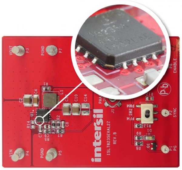
All three of the ISL7823x devices are available in 5mm x 5mm 16-lead wettable flank thin quad flat no-lead (WFQFN) packages with an exposed pad for improved thermal performance. Because they offer 3A, 4A or 5A output current options, it’s easy to upgrade a design just by dropping in a new IC with no change in the PCB layout. This saves development costs and time! In addition, the wettable flankpackage enhances verification of automotive manufacturing quality as it enables optical inspection to verify proper soldering joints as shown in Figure 7.

Conclusion

Today’s growth in sophisticated cockpit electronics is requiring higher current power supply regulation at lower voltages. POL power supplies need buck regulators that generate very low voltages for GPUs and other higher current devices powered from a primary supply rail of 5V or 3.3V. System designers want to save design time by using the same POL devices across their entire vehicle line up from entry-level to luxury car models.

To achieve these goals, we’ve shown that synchronous buck regulators that use high-side P-channel MOSFETs and other architectural enhancements deliver the optimized secondary power rail solution demanded by power supply designers. With auto manufacturers driving for higher levels of innovation, they look to their semiconductor suppliers to deliver the flexible, rugged and higher performance ICs that can help them realize their system design goals.

- Advertisement -